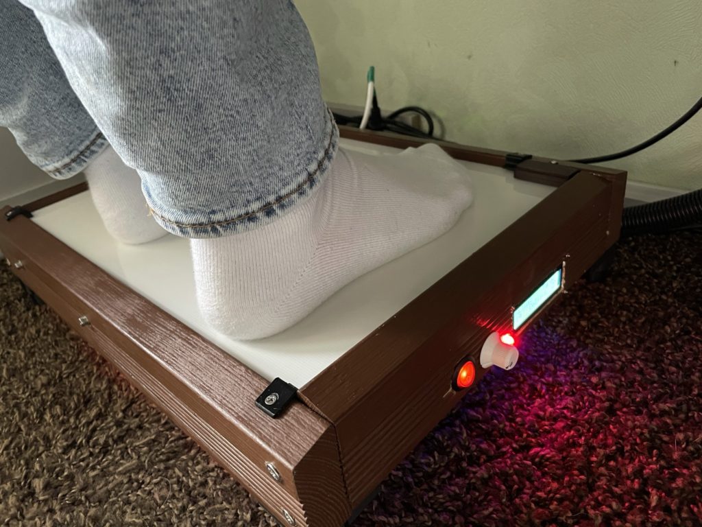
Last winter was really rough, a couple of weeks below 0 degrees celsius and the ground didn´t even thaw at daytime when it was sunny.
As my office was in the basement of the house, which was hard to get heated to a common room temperature, i felt the cold crawling from the bottom. So after several hours sitting in front of my computer without physical activities, i felt like our dog when she had to go outside barefoot in the snow.
At the same time I´ve found a heated bed PCB from my first 3D printer and thought that this would be the perfect solution for the cold season to heat me up from the bottom. As the heated bed wouldn´t store the heat for long time, I planned to use a small stone tile as heat memory.
cold feet and toes
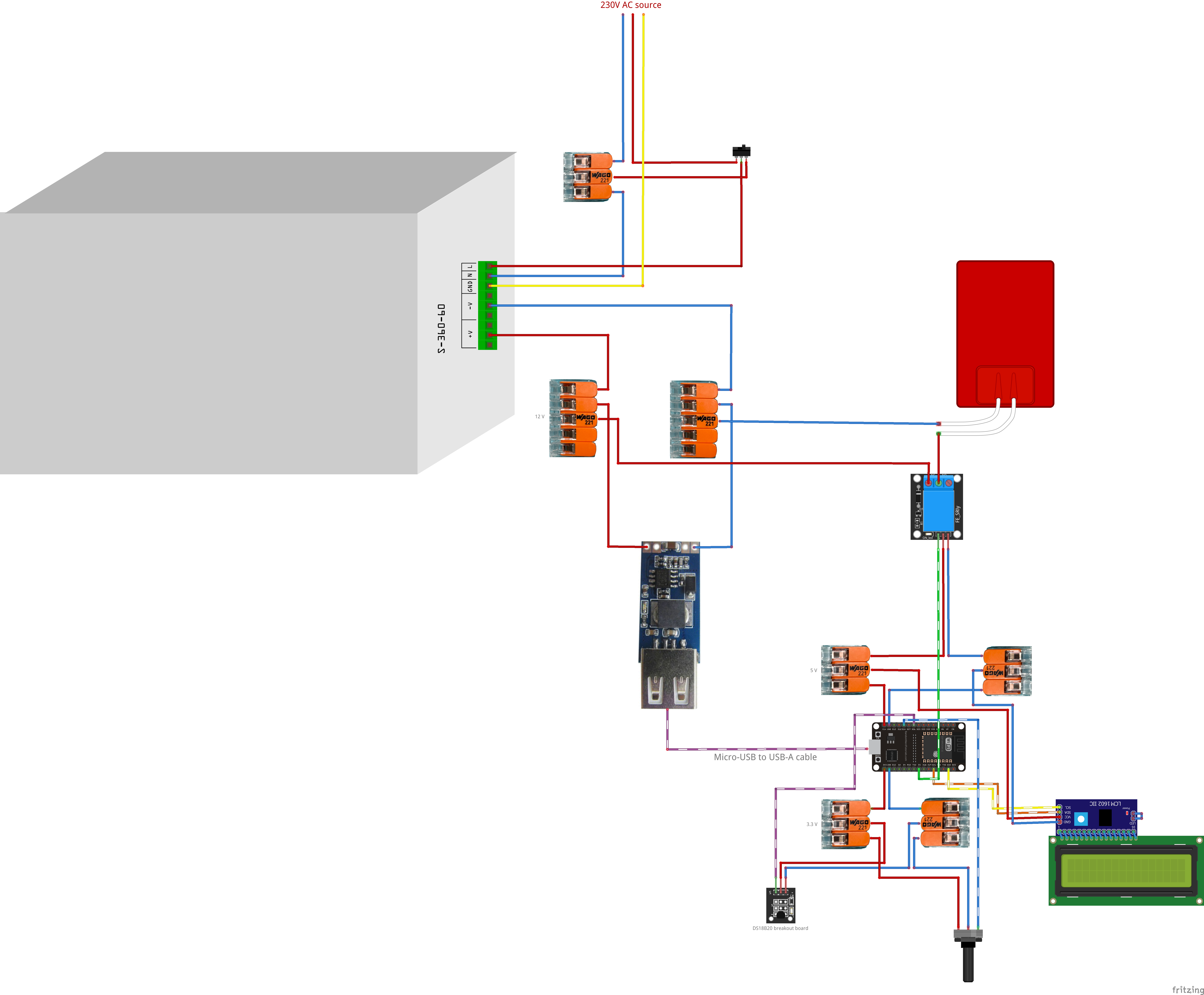
(Click to open circuit diagram)
Design the circuits and coding
At first, I selected a microcontroller for this project, which connects to all the different sensors and relais and runs the program logic to control everything. I´ve chosen an ESP32 module – even if it’s a little bit overpowered, it´s still affordable and offers more than enough GPIO pins for this project.
As I´ve bought from time to time multiple electronical starter sets (Containing different sensor and switches), I already owned a good selection of components for this project.
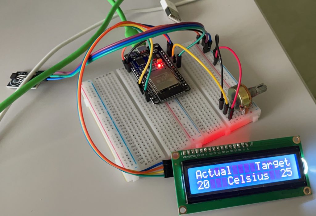
I definitely needed a user input module, to make the temperature choosable – so I picked a simple potentiometer that I already owned. There would be also other solutions like two buttons (for raise & lower temperature) but people like to rotate things.
Beside of that, I also added a graphical UI to display current temperature and target temperature (LCM1602 LCD module). To measure the temperature, I´ve picked the DS18B20 (breakout board version).
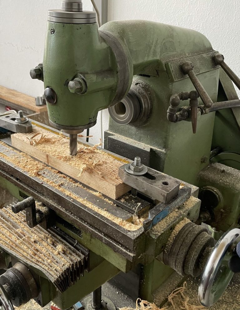
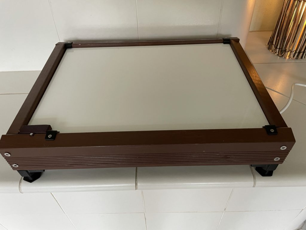
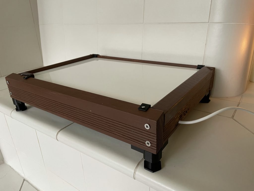
As the 3D printer’s heated bed PCB is brittle and wobbly, I decided to build a wooden frame around it, to make it more protective and stable.
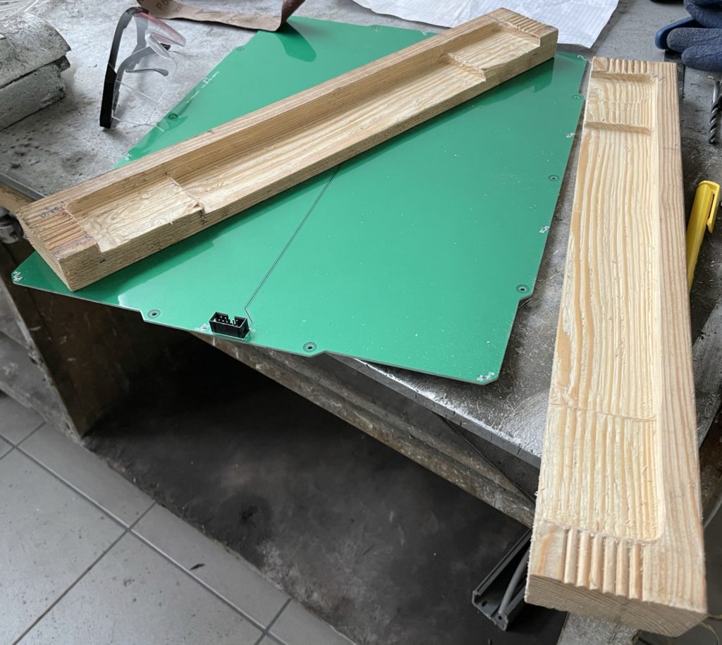
As I´ve access to a milling machine, I´ve cut common squared timber pieces like in the following schematic- so that i can assemble the heated bed PCB from the bottom onto the wooden frame.
Half an hour later, both side frames were done.
Afterward, I crafted the front and side frames, where I will embed the LCD panel and buttons later. Then I sanded the edges of the wooden frame and painted it with green wood color.
Complete the assembly
As we have to put the electronic stuff, like the 12V transformer (which gets hot in minutes) on the bottom of the construction, I made some concerns about the ventilation of these parts.
With the help of my 3D printer, I printed four adjustable feet (Thingiverse Link) to get more space on the bottom for better ventilation.
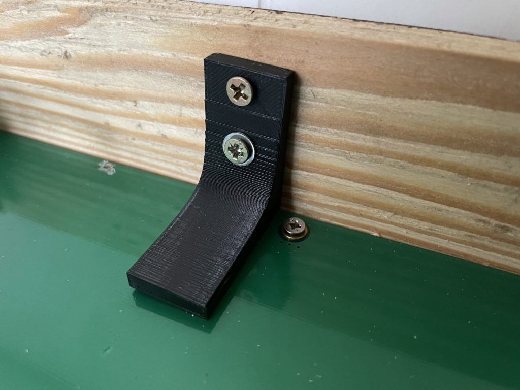
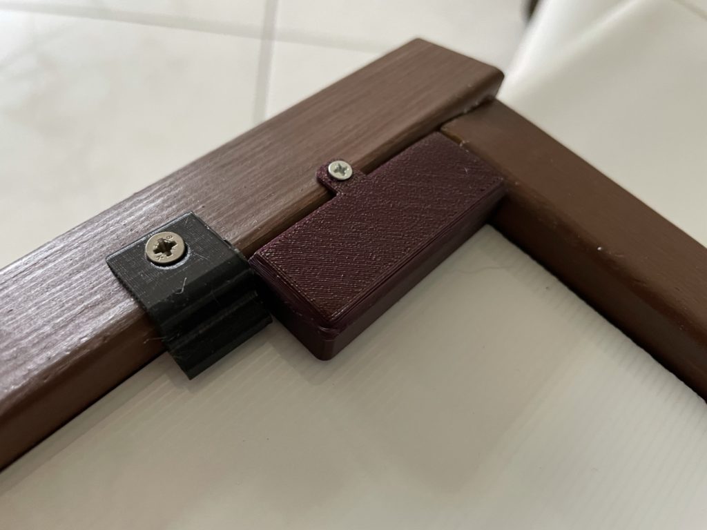
Then I´ve printed some 90° angles (metal angles were used up) to mount the PCB onto the frame and stop it from falling down. These angles will also carry the weight of the stone tile later.
As the frame and the whole construction was stable, the next step was to connect all of the electronical parts together. (See circuit diagram before)
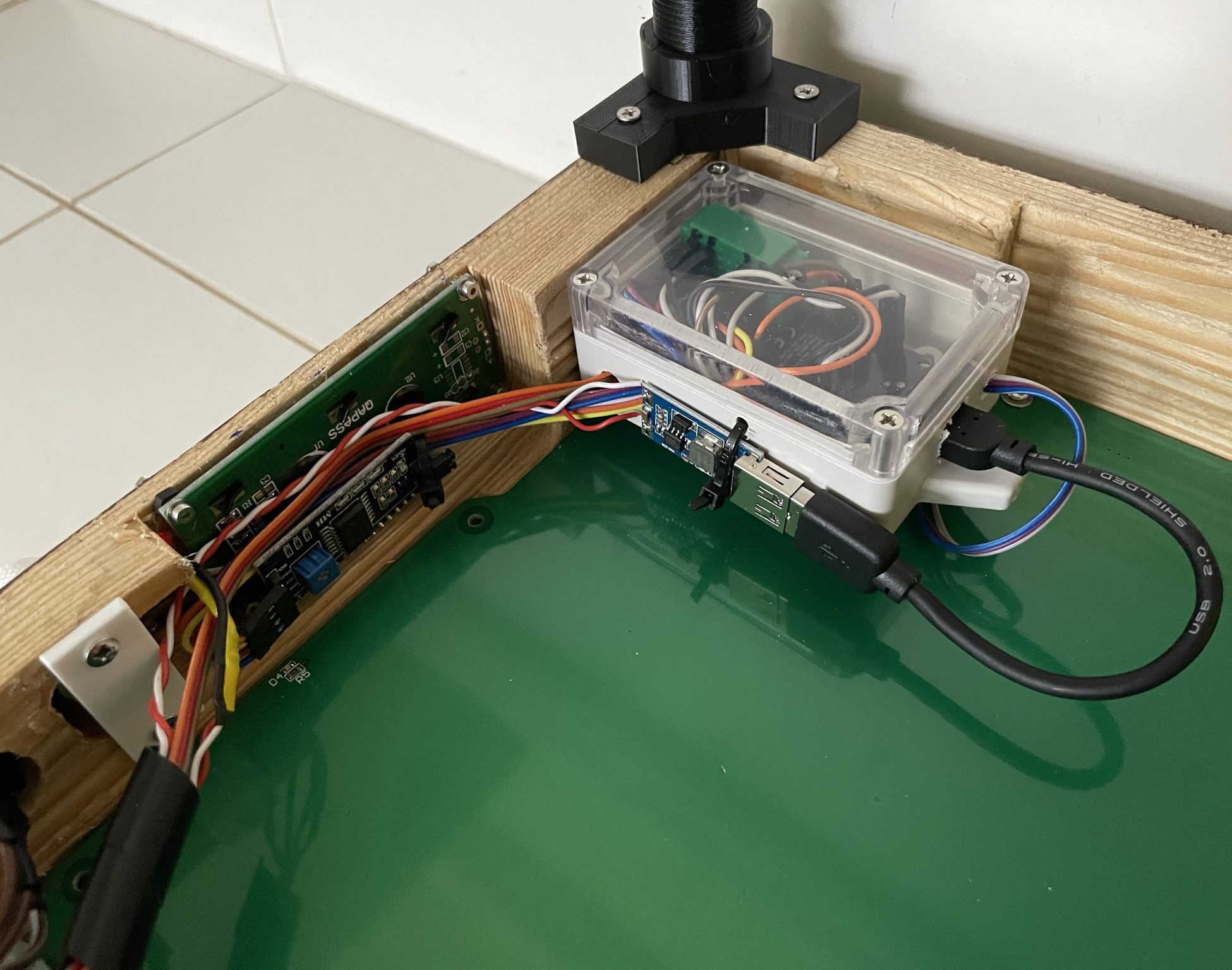
I´ve embedded the ESP32 (the brain of the whole thing) in a small electronical case, to protect the GPIOs to get detached unintentionally. You can see the USB cable coming out of the box, this delivers the voltage to the ESP32, which was transformed to 5V before.
As I´ve measured and milled the cutout in the front of the frame before, I could easily insert and mount the LCD panel into it.
I´ve also drilled some holes into the front-frame for the potentiometer and power button and mounted them with simple 3D printed parts which I´ve designed quickly (Uploaded to Thingiverse). (The white part in bottom left of the image)
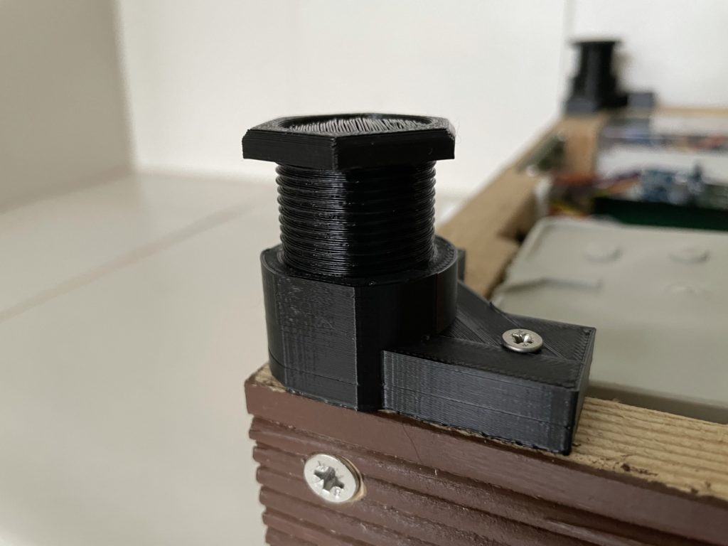
The last step of the setup was to mount the DS18B20 temperature sensor module to the top of the stone tile. I´ve printed a small cover, made of PETG plastic, to protect the tiny sensor from being stamped by someones feet.
ESP32 box (Click to enlarge)
DS18B20 temperature sensor with cover
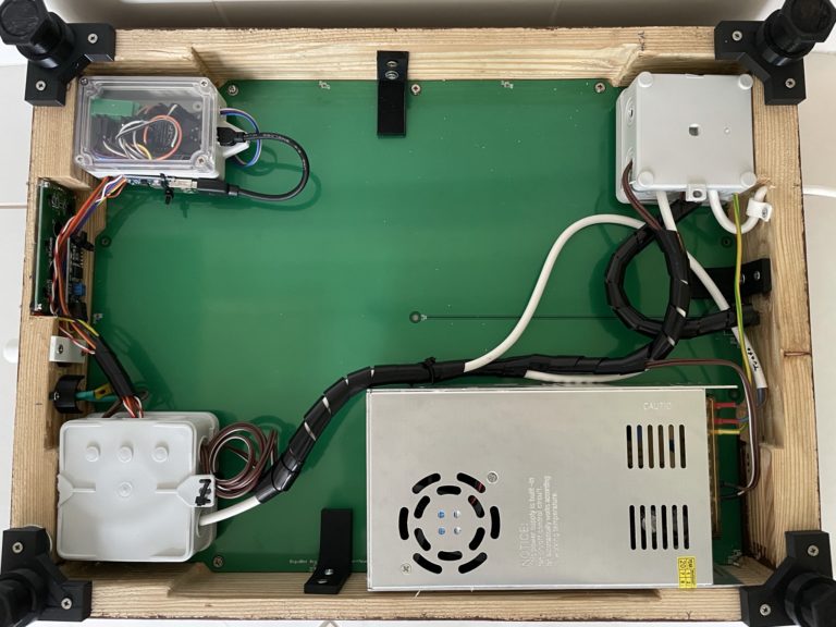
I´ve added two more electronical boxes (bottom left and top right), to keep the cable distributors and junctions protected.
Some black cable sleeves were used to keep the cable salad together and cleaned up.
Heat me up!
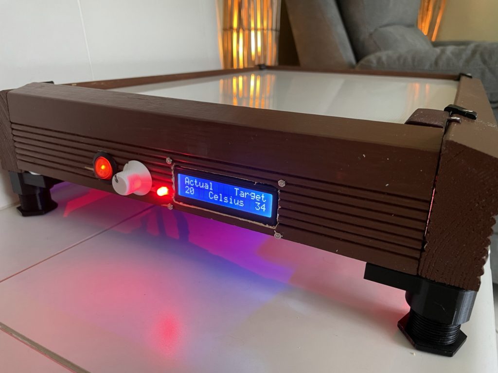
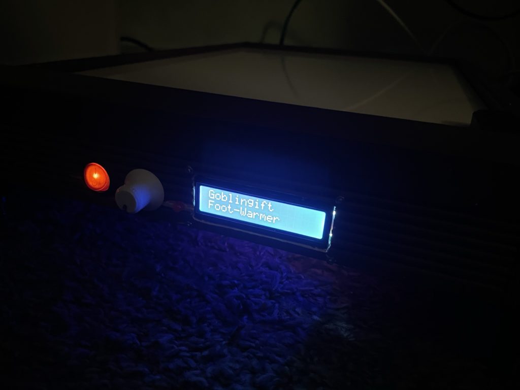
After weeks of drilling, milling and with good willing, I completed my construction and started it by switching the power-button. Then the ESP32 starts up in 2-3 seconds and the LCD panel shows the current temperature and the target temperature.
By rotating the potentiometer, i can select the target temperature (35° degrees celsius is fairly enough). It takes 2-3 minutes to reach this temperature, then it will go in idle mode until the temperature is some degrees below. Thanks to the stone tile it saves the temperature for at least 7-10 minutes until it heats up again.